
Introduction
It's time to continue my summer project of setting up some outdoor LED lights. Previously, I set up and updated the Ericsity controller with WLED.
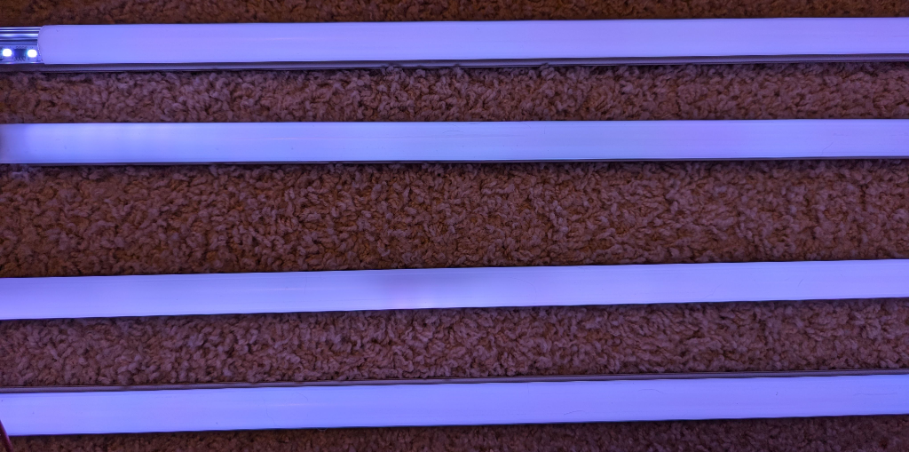
I am putting up approximately 20 meters - 65 feet - of LEDs. Total this will be nearly 2,000 individual LEDs and approximately 665 individually controlled LED segments (3 LEDs per segment). This will take more power than the little controller can handle. To demonstrate the problem of powering all of these LEDs with only the controller, look at this image:

These strips are wired with the end of one strip connected to the start of the next. The top strip is connected directly to the controller. The one below is the end of strip two, followed by the start of strip three and the bottom is the very end of the full run of LEDs. The lights are all set to the same color, but as you can see they clearly aren't the same color. The voltage drop across 65 feet of LEDs means that the LEDs are the end can't get enough power to match their earlier siblings.
Power Injection
The solution to this specific problem is to inject power into the LED strips. I picked up some WAGO connectors and a NUOFUWEI power supply. I also had some 18 gauge wire on hand. With this power unit, I can easily set up three injection points.
The goal was to inject power at the start of strip 1, right where the controller is connecting in the image above. Then inject between strips 2 and 3, in the middle of the run. Finally, I injected power at the end of strip 4. With these three, equally spaced injection points, I was able to get a nice uniform color across the entire 20 meter run.
Problem Solved! Right?
Not exactly.
Turning off the PSU
WLED controls the lights, but doesn't control the power supply with this wiring setup. Turning off the lights within WLED does turn off the LEDs, but the power supply continues to run. It's not drawing at full load, but it is drawing power and the cooling fan is active. It's noticeable and unneeded. I want a way to turn off the power supply AND the LEDs at the same time.
I can't power the WLED controller from the large power supply to do this, because if I turn off the power supply that'd also turn off the WLED controller. I'll need to power the WLED controller independently from the lights. Fortunately, this won't be a problem.
The next step is figuring out how I can use WLED to control the larger power supply. Fortunately, WLED has the ability to control a relay, which I can use to control the power supply. The Ericsity controller also has two output data pins. While I don't think the second one was built in to control a relay, it works perfectly here.
Wiring
I purchased a HiLetGo relay so that I could toggle the larger power supply on and off. To do this, it's important that the data line and the ground are common among the controller, the power supply and the LEDs.
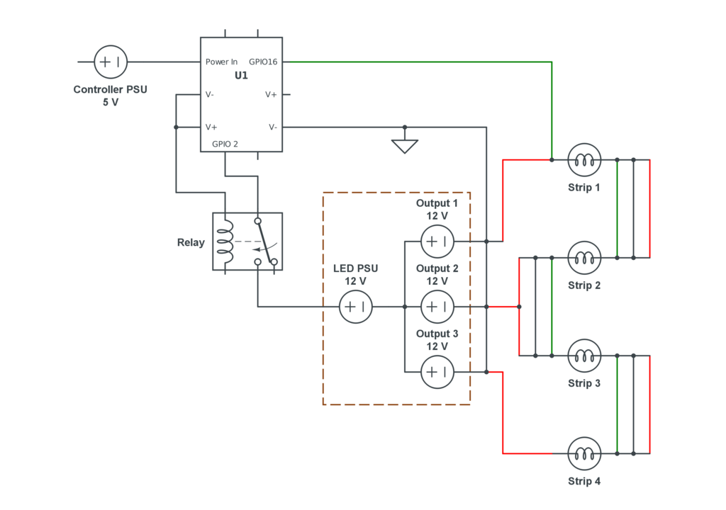
The diagram above is a rough schematic of how I wired this. The controller sends data, but not power, to the LEDs. Data was on GPIO 16. The important part here is that the data line is shared across all of the strips. I did not need a signal booster for my project, and because I'm about to use the second exposed data channel for the relay, I had to ensure that this single channel could send a signal down the entire length of the strip. Fortunately, I didn't have any issues.
The wiring ground was tied into the PSU and the LEDs as well. The common ground is important.
On the other side of the diagram is the relay. I put this relay between the wall and the PSU. When WLED sent an ON signal, it would close the relay, turning on the PSU and the LEDs. GPIO 2 was tied to the relay and within LED Preferences, the Relay Pin was set to GPIO 2.
One quick power cycle from within WLED is required at this point. Press the power button in the UI to turn everything off, press it once more to turn it on. As long as the PSU is plugged into the wall, you should hear it fire up and see the LEDs turn on. If you press the power button again, the LEDs turn off, the relay clicks, shuts down the PSU and only the WLED controller remains active.
Success
With the relay in place, the LEDs don't draw phantom power while off because the PSU isn't active. The added benefit, at least for this specific power unit, is that the fans aren't running constantly so it's not as loud. While this will eventually be outside, I'd still prefer to not hear the fan when the lights are off. While they are active it's not going to be bothering me, because I'll likely have music playing for the sound reactive features which will easily be louder than this fan.
The next step in the project is going to be to get this set up outside.